
Design a Basic VPC Architecture
This was my first experience learning about VPCs and designing one. I had previous knowledge of networking, but not how it is applied in the cloud. The challenge was both thrilling and incredibly interesting.
1 — Requirements
2 — Architecture Design
3 — Conclusion
1 - Requirements
- VPC Design: Create a VPC with a specified CIDR block.
- Subnet Design:
- Two public subnets (one in each AZ).
- Four private subnets (two in each AZ) for the application and databases.
- Internet Connectivity:
- Internet Gateway for public subnets.
- NAT Gateway in public subnets for private subnet Internet access.
- Route Tables:
- Configure route tables for proper routing between public and private subnets.
- Security:
- Restrict database access in the private subnet to only application servers.
- Documentation:
- Provide an architecture diagram and explain the design choices.
2 - Architecture Design
Components
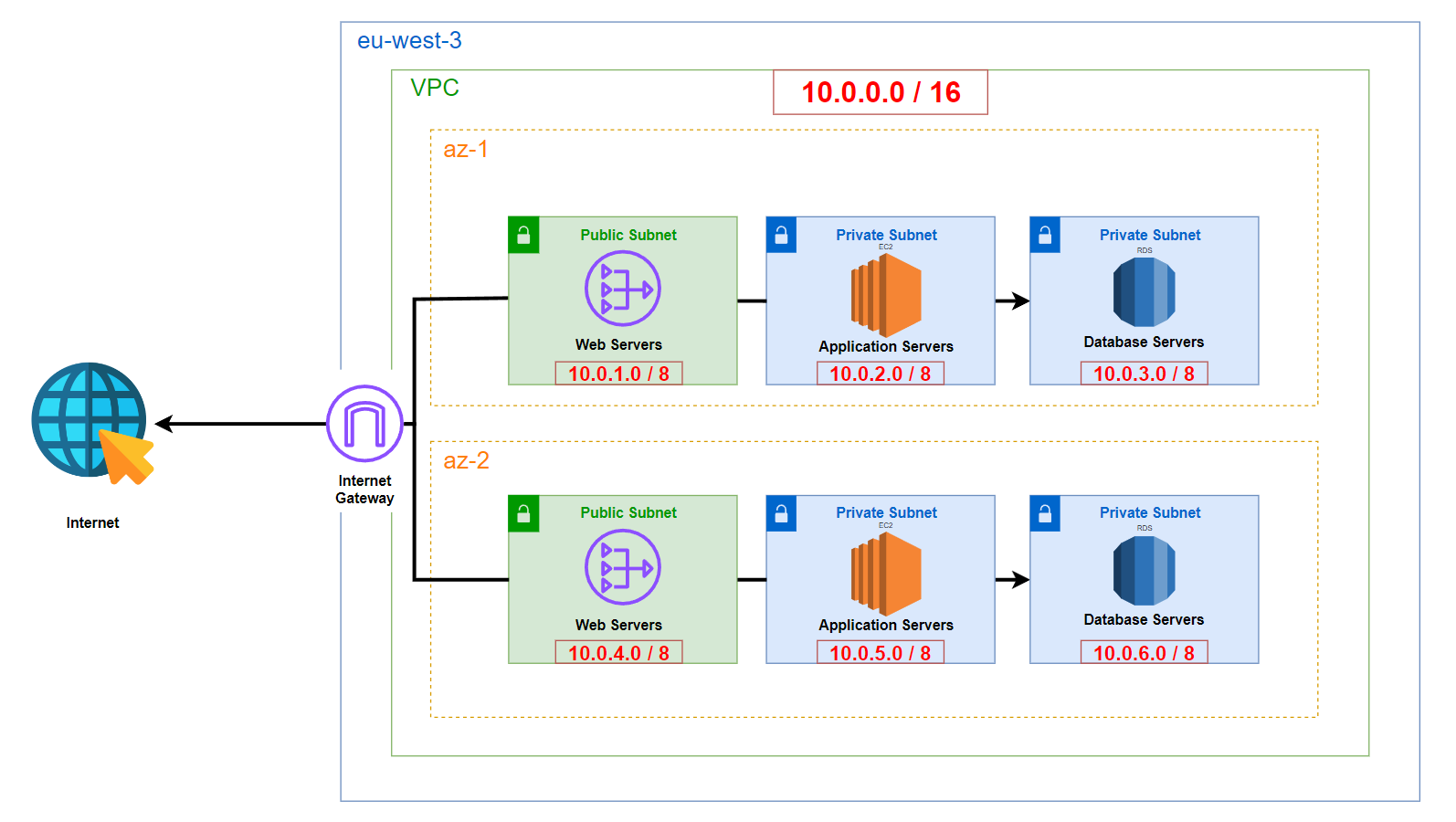
- Region: The architecture is deployed in a single AWS Region:
eu-west-3(Paris). - VPC: A single VPC containing all resources across two Availability Zones (AZs).
- Availability Zones: The resources are distributed across 2 AZs to ensure high availability and fault tolerance.
- Public Subnets: 2 subnets, one in each AZ, with Internet access for the NAT Gateways.
- Private Subnets: 4 subnets (2 per AZ) isolated from direct Internet access for application servers and databases.
- Internet Gateway (IGW): A single Internet Gateway attached to the VPC to provide Internet connectivity to the public subnets.
Network
I selected a large CIDR block for the VPC: 10.0.0.0/16. This provides a substantial number of IP addresses (65,534 usable addresses) to accommodate current and potential future needs. Although the theoretical maximum is 65,536 addresses, AWS reserves the first four and the last IP addresses in each subnet, as documented here:
- 10.0.0.0: Network address.
- 10.0.0.1: Reserved by AWS for the VPC router.
- 10.0.0.2: Reserved by AWS for the DNS server.
- 10.0.0.3: Reserved by AWS for future use.
- 10.0.0.255: Broadcast address.
Given the architecture requirements, we need six subnets, which I have allocated as follows:
| Name | Subnet | Mask | Number of Addresses |
|---|---|---|---|
| az1-public-subnet | 10.0.1.0 | /24 | 251 |
| az1-application-subnet | 10.0.2.0 | /24 | 251 |
| az1-database-subnet | 10.0.3.0 | /24 | 251 |
| az2-public-subnet | 10.0.4.0 | /24 | 251 |
| az2-application-subnet | 10.0.5.0 | /24 | 251 |
| az2-database-subnet | 10.0.6.0 | /24 | 251 |
Each /24 subnet provides 251 usable IP addresses (256 total minus the 5 reserved by AWS). This design uses a large range to facilitate scalability and operational simplicity, though in practice, smaller subnets would suffice for many use cases.
Route Tables
The routing setup is straightforward:
Public Subnets: The public subnets require a route to the Internet Gateway to allow inbound and outbound Internet traffic.
| Destination | Target |
|---|---|
| 0.0.0.0/0 | IGW |
| 10.0.0.0/16 | Local |
App Subnets : To allow instances in private subnets to access the Internet for updates, we use a NAT Gateway. The other entry allow to communciate with all the resources presents within the network.
| Destination | Target |
|---|---|
| 0.0.0.0/0 | NAT |
| 10.0.0.0/16 | Local |
DB Subnets : DB don’t need direct access to Internet. Only our application can access our database.
The 0.0.0.0/0 route is a catch-all route, directing traffic to the specified target when no more specific route is found.
| Destination | Target |
|---|---|
| 10.0.0.0/16 | Local |
High Availability
Our architecture is designed for resilience and high availability by distributing resources across two Availability Zones (AZs). If one AZ experiences a failure, the other AZ can continue to handle traffic seamlessly, ensuring uninterrupted service. While the architecture could be extended to span multiple regions for even greater fault tolerance, this might be excessive for a basic application of this scope.
Security
Security is enforced through the following measures:
- Private Subnets: Application servers and databases reside in private subnets, preventing direct Internet access. Any Internet-bound traffic must go through the NAT Gateway, providing control and monitoring over outgoing communications.
- Security Groups:
- Application Security Group: Controls inbound and outbound traffic for the application instances.
- Database Security Group: Configured to only allow inbound traffic from the application security group, ensuring that the database can only be accessed by the application servers. This provides a more granular level of security compared to Network Access Control Lists (NACLs).
- NAT Gateway: Used to facilitate outbound Internet access for instances in the private subnets without exposing them directly to the Internet.
By combining private subnets, NAT Gateways, and tightly controlled security groups, we maintain strict control over network traffic, thereby enhancing the security posture of the application and database.
3 - Conclusion
This architecture leverages AWS best practices to ensure a scalable, highly available, and secure environment for the web application. The design not only meets the current requirements but also provides flexibility for future growth.